A load cell on its own delivers a very small signal – typically a few millivolts per volt of excitation. Before that value reaches a controller, it normally needs an amplifier, a shielded cable and a carefully planned grounding concept. With a single measuring point that is no problem. With eight measuring points on one machine it becomes half a control cabinet.
A load cell with CANopen turns the principle around: the signal conditioning sits inside the transducer, and what comes out is no longer an analogue signal but a finished digital measured value on a two-wire bus.
What CANopen actually is
CAN is a serial bus originally developed for automotive use: two twisted wires, CAN-H and CAN-L, transmitted differentially and therefore robust against interference. CAN itself only defines how bits travel along the wire – not what they mean.
That meaning is supplied by CANopen, the application protocol on top, standardised by CAN in Automation (CiA 301). Four things matter most in practice:
- Node ID: every device on the bus has its own address. It is therefore unambiguous which reading comes from which transducer.
- Process data (PDO): the measured value is sent cyclically and without being requested – this is the actual payload channel.
- Parameters (SDO): settings such as filtering, zero point or transmission rate are read and written over the bus, not with a potentiometer.
- Diagnostics: a heartbeat shows that a node is alive. If a transducer fails or reports a fault, the controller sees it actively – it does not have to infer it from an implausible analogue value.
What this means at the force transducer
The amplifier disappears. Bridge excitation, amplification and digitisation all happen inside the transducer. That removes one device per measuring point from the cabinet – along with its wiring, its footprint and its calibration.
The cable stops being critical. An analogue signal of a few millivolts reacts to cable length, contact resistance and nearby frequency converters. A digital bus value does not: it either arrives or it does not, but it does not drift quietly.
Several transducers on one line. CANopen devices are daisy-chained. For a hopper weighing system with four cells, or a weighbridge with eight, that means one cable instead of eight – and the summation happens in the controller, not in a junction box.
Every cell stays individually visible. This is the point that pays off most in the field. With analogue cells wired in parallel you only see the sum. Over the bus you see each cell on its own – and with it an uneven load distribution, a jammed support or a single drifting measuring point, long before the total looks suspicious.
An example from our production: LRGA 100 kN

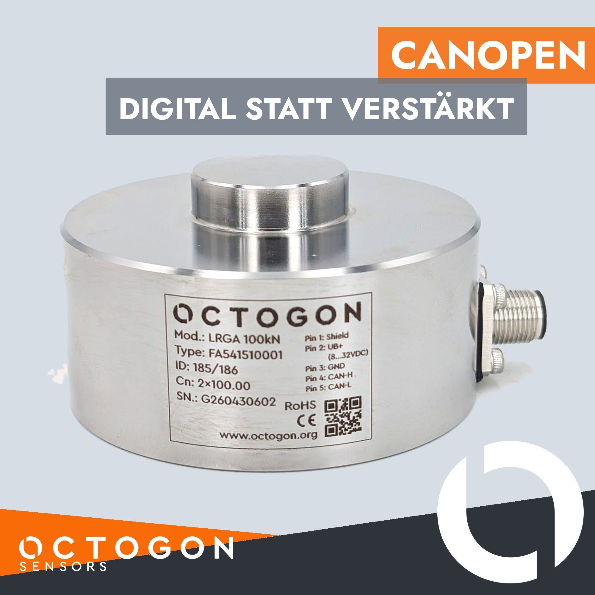
The photo shows a load washer from our own production with a CANopen interface. What its nameplate says tells you a lot about the design:
- Mod.: LRGA 100kN – 100 kN rated capacity in compression, annular design with a central load button
- Cn: 2×100.00 – two rated capacities, meaning two mutually independent measuring bridges in the same housing
- ID: 185/186 – accordingly two identifiers, one per channel
- 8…32 VDC – a wide supply window that covers 24 V installations as well as 12 V supplies
- M12, five-pin – pin 1 shield, pin 2 UB+, pin 3 GND, pin 4 CAN-H, pin 5 CAN-L
The M12 connector is more than a convenience: it makes the transducer replaceable in service without opening a terminal box and without re-terminating any wires.
Two measuring bridges: why redundancy
Two separate bridges with separate connection points are not a luxury but the basis for safety-related applications. Standards such as EN 62061 and ISO 13849, both built on EN 61508, require an architecture for higher safety levels in which a single fault does not go unnoticed.
Two independent channels deliver exactly that: the controller compares both values. If they diverge, there is a fault – and a detectable one, not a silent one. Separate connection points additionally reduce common-cause failures, for example a damaged connector that would otherwise corrupt both channels at once.
You will find more on the subject and on the levels that can be reached on our page Functional safety SIL | PL.
CANopen, IO-Link or analogue after all?
All three routes make sense – just for different jobs.
- Analogue (mV/V, 4…20 mA, 0…10 V): the right choice for a single measuring point, for very high resolution requirements with an external precision amplifier, and anywhere the controller only offers an analogue input in the first place. Matching electronics can be found under weighing transmitters and strain gauge amplifiers.
- IO-Link: strong for individual sensors on a fieldbus master, with simple parameter setting and automatic device replacement. How it works is described in our article How does IO-Link work?, the available designs under IO-Link load cells & sensors.
- CANopen: ahead as soon as several transducers work together, cables get long, diagnostics are wanted or redundancy is required.
If you are unsure which route suits your controller, ask us. The decision depends less on the sensor than on the installation around it. Our page Profinet & other fieldbuses gives an overview of further bus systems.
Available designs
Digital interfaces are not a separate product family here but a variant. In principle all our designs can be built with integrated electronics – from the load washer as in the example, through compression load cells and tension and compression load cells, to the load pin. The full overview is under load cells & force transducers.
How a load cell works in principle, and what to look for when selecting one, is explained in our article How does a load cell work?.
Do you need a cell with CANopen?
Rated capacity, design, number of channels and interface are matched to your application – including as a custom version. Tell us which load is being measured, how many measuring points come together and which controller takes the data.
Write to office@octogon.org, call +43 676 3628453 or use our contact form. On request we calibrate the cell to ISO 17025 before delivery.